Thursday, February 26, 2015

Lightspeed Ignition Part 1

Starting the Dual Lightspeed Ignition Install.

Here is a picture of all the parts that come in the kit. Sparg plugs, wires, the two control boxes, engine mounts for the sensors, and several other things.

I started with the step that made me the most nervous....drilling and tapping this VERY epensive engine. First you need to remove one of the propellor bushings that are pressed into the crankshaft. I used a wrench and two c-clamps....and some gentle taps from the hammer. Not gonna lie this was a pain in the butt.

With the bushing removed I marked and drilled the location needed for the engine sensor mount. I taped off the drill to mark the depth....I really didn't want to go too deep....that would be bad.

Once I drilled the holes I could tap the holes in the engine block.

After the engine was drilled and tapped I could try out the mounts. They need some tweaking to even make the installation work; which is a bit annoying when you spend this much on an ignition system. But I get that they try and make it work for every engine.

Next I started making a mount plate for the ignition coils. Here is the intitial test fit.

After the test fit I learned where it could be trimmed up. Then I riveted the mount flanges in place, painted it with high temp paint, and bolted it to the engine mount using Adel clamps.

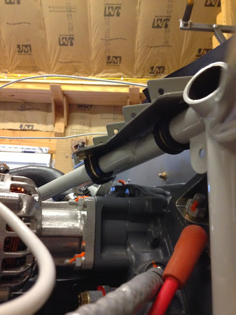
Here is a view from the under side to see the Adel clamps. Three Adel clamps, one of which is on the angled bar, allows for a solid install.

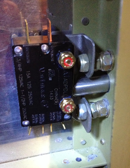
With the plate in place I screwed the ignition coils in place.

Ignition coils screwed in place with mechanical locking nuts, not nylon locking nuts. They're better for high temp areas.

The spark plug wires that come with the kit aren't long enough for half of the install so I had to make my own....actually very easy to do.

Here is the initial test fit of the spark plug wires I made. They still need to be secured in place.

Other side....you can see I started securing the wires in place with little tabs that attach to the lower valve cover screws.


My helper.

Firewall Forward Stuff

With the lighting system done, I finally got to go back to working on the firewall forward stuff.

I installed covers to the old magneto locations (these covers come in the lightspeed igniton installation kit).


I made some firewall feed thrus. These are my own design made from a few cheap parts from Aircraft Spruce. They sell aluminim flanges for ducting that I riveted to the firewall using stainless steel rivets. Then I pushed some firesleeving tubing through the ducting. Everything was installed using either fire barrier caulk or hight temp RTV. Once the wires are ran through the tubing it will get filled with high temp RTV to create a fire resisant and air tight seal.

I installed the fuel lines. My fuel lines are from Bonaco and are fire sleeved. Actually all of my fluid lines that are forward of the firewall are firesleeved. I snapped this picture to show that I secured my fuel line as far from the exhaust as possible using an Adel clamp.

This is one of the oil lines and does not take the standard route of up and over the engine mount. Instead it snakes around under the oil cooler air intake tube. This route just worked better for me.

Here you can see that the manifold pressure line doesn't take the normal route either. Typically this is installed on the complete opposite side of the engine. But since my MP sensor is mounted to the manifold on the firewall it was easier to run it from the LH aft cylinder. Also, this allowed me to use the stock line.

I got the wires ran to the shunts and ANL fuses that come from both of the alternators.

I got the wires running from the power feed thru to the starter solenoid and then on to the starter.

Tail Avionics Shelf

I needed to come up with some kind of shelf to hold the avionics that needed to be in the tail. My goal was to put as much of the avionics in the nose as possible, since the CG on this aircraft can only go aft as you load it. But it made wiring for the lights simpler by just running them aft so that is where the LCU needed to be installed. Also, the ELT needs to be in the back and I decided to install the GDL 39R (ADSB) box in the tail as well. This happened for two reasons: it is close to the antenna and it only has four wires that needs to run up front.

To minimize the alterations to the existing structure I decided to use the four aft screws in the bell crank plate and install two small angles on the frame and stringer. The trick was getting everthing level.

This shows the tray installed and all the wiring in place. The GDL 39R isn't installed yet but it will be installed on the bottom upside down.


Here youi can see a small fuse block installed behind the LCU this holds the fuse for the lighting system since it will connect directly to the battery. Aslso you can see the edge of the ADSB antenna doubler on the LH side of the picture.

Lighting Control Unit

I'm still playing catch up and trying to get the blog updated. I'm also still on the subject of interior lighting. After finishing running the wires I needed to buckle down and build the lighting control unit (LCU). This little red box looks important but really isn't. It controls the interior lighting system. Ed Kranz and I worked on designing the electrical schematic that went into the entire system and mainly in the box. Ultimately our plans differed just enough that we had to create our own schematics. I didn't have any fancy program to create my schematic so I "old schooled" it and starting drawing by hand. The LCU provides power distribution and signals for when doors open and provides a time out and shuts the power off to the lights if you leave them open.....basically it makes the interior lights of the plane like your car.

Here is  my hand drawn schematic. This worked great for me and allowed some kind of documentation as to what was done. ...Don't worry the rest of my avionics has a professional schematic drawn out : )  


I got a fancy little box to put the relays and circuitry in. I glued some standoffs in place and started soldering. 


I cut a hole for a D-Sub connector that provides all of the needed connection points. I'm pretty happy with my little "LCU" it looks like a legit piece of equipment.

Monday, February 23, 2015

Wiring and Door Switches

Yeah I know I'm really slacking on posts. I'm very far behind. Of course anyone reading this a year from now will just flow from the previous post to this one and think I didn't miss a beat. But if you look closely my lost post was in November and here we are almost at the end of February. Shameful I know. But I have been working on the plane VERY hard, so no worries. I have a lot more posts to put up after this one but no guarantee as to when it might happen.


So my last post we talked about my interior lighting and wires and such. This post continues on that.

Here are the DPDT switches I'm using for my doors. They control a ground and power loop that flips a relay to turn power on to the control box and turns on the light for the door that is opening. Sitting beside the switch is the small bracket that I made to install the switch.

The bracket installs on the aft side of the door frame and you can see how the pin engages the switch (opening the circuit) when the door is closed. It was a little difficult getting the wrench in there and I did have to use thin nuts instead of the standard thick size.

I ran wire through the rear seat support frame to get to the LH door and this is where the baggage door sensor is going to install...see it hanging out of the tunnel.

I also worked more on the tailcone wiring. I made a connector for the pitch trim servo connection.

Close up showing the connector and the small bracket that will hold the D-sub I'm installing on the pitch trim servo wires.