Friday, August 29, 2014

Completed Structure Overview (1320.25hrs)

I just got caught up on a lot of posts and I'm just going to report my times here. It's becoming increasingly difficult to log the times into categories because you start to do a lot of different tasks at this point in the build.

August Times and Dates
2    -5.0 hrs- spinner and prop install
3    -5.5 hrs- cowling work
9    -5.25 hrs- cowl work...im pretty sure
10  -4.0 hrs- cowl stuff maybe
11  -1.0 hr- cowl hinge work
12  -1.25 hrs- cowl hinge work, installed prop governor
13  -1.5 hrs- cowl hinge work, air ramps
15  -7.0 hrs- engine work, cowl work, prop stuff, other stuff im sure
16  -4.75 hrs- same as above...too hard to document now
17  -3.25 hrs- engine stuff...i think

Sorry for the lack of detail but I can't promise it's gonna get better.

Total Time so far
1320.25

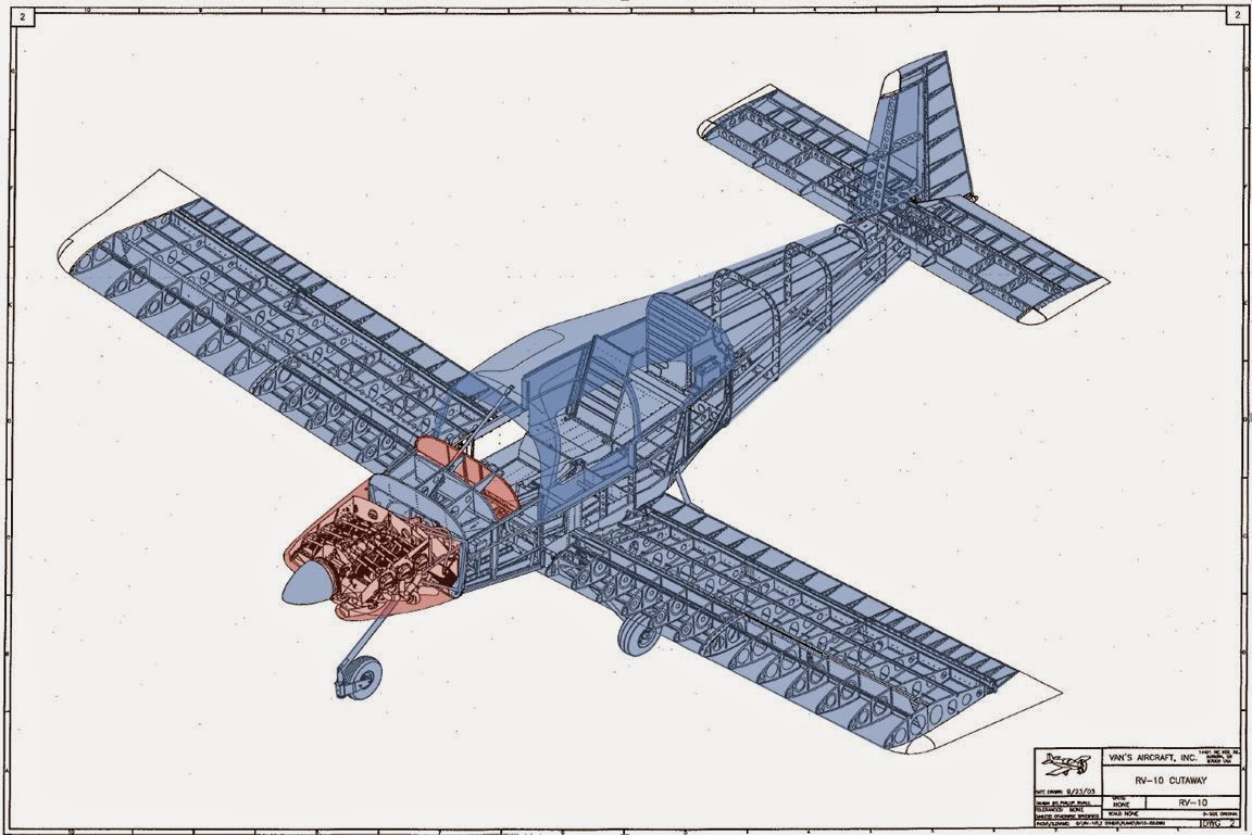
Red is in work. Blue is complete. ...as you can see eventually this little diagram won't be of use anymore.

Filtered Air Box

Catching up on posts still.

The filtered airbox at first seemed like it was going to be a lot of headscratching trying to figure it all out since the instructions are a bit lacking in the information department. But after I saw some pictures of what the end product was supposed to be it became pretty easy.

First I fluted the metal top to match the fiberglass bowl.

I then clecoed it in place allowing the filter sit just a little above the top so it would be completely closed out when I screwed the top plate into place.

I unbolted the closeout panel for the throttle body and let the little bit of oil drain out. Then I temporarily installed the throttle body in place for all the fitting. I didn't do a permanent install since it will have to come back off again when I fully drain the storage oil. The picture shows what is pretty close to the final install. You can see the cut out on the side that is required to clear the arm of the throttle. Pretty simple stuff. Cut the clearance out and match drill.

The air intake in the lower cowl has to be extended inside to meet up with the FAB. So they supply a foam block to help create the extra internal lip. I cut down the block to fit inside the lower cowl.

You're supposed to use the block to form the internal extension. This is a pic of the foam block in place with the lower cowl installed. You do need to trim the front of the FAB to allow for clearance of the lower cowl.

I then started carving out the inside of the foam block to make a "tunnel" from the lower air intake to the front of the FAB.

This produced a ring like this. ....this story will continue later....still working on this part.

I want to able to open and close the alternate air door (stock design only allows you to open and not close) from inside the cockpit. So I cut out my hole in the bottom of the FAB and then using a scrap piece of aluminum (taped up for a release agent) formed what will become a track for the air door to slide  back and forth in. I also fiberglassed my drain tube in place.

Thursday, August 28, 2014

Started Cowling

Continuing to catch up on the posts so I'll just let the pics go through everything.

As you can see the cowlings don't line up very well from the factory. The whole section is really just about getting them cut to size and having everything match up in the end. The instructions seemed to do things backwards then the way I thought you'd do them. So after thinking things through I decided to just approach cutting and fitting these like a wood working project. After I got in that mindset things went really well.


One thing I should note is that I made the cut out in the lower cowling for the front landing gear leg much wider than what the plans call for. The plans dimension is so tight I couldn't even install the cowling over the landing gear. So I increased it by (I think) about 0.75".

So I couldn't use the table saw to make a nice straight cut like I would for building furniture, so I broke out the laser level to mark a straight line from the ridges of the inner circle to the outboard edges of the cowling openings. I used the ridges as a guide to know when I had the cowling level. I then trimmed down the outboard inlets flush to the lines that were made from the laser level leaving the sides sticking up to be cut later.


With the front edge cut the two halves of the cowl could rest against each other and I was able to tape them up into place. First I taped up the bottom cowl and got it into place. I used some spacers up front against the spinner and then just duct taped the cowling to the engine to suspend it in place. The aft part of the cowling rested against fuselage skin.I then used an edge finder, just like I did with the doors, to mark the edge of the fuselage onto the cowling. I then cut the cowling along the line and re-installed it with a few clecoes into the hinge to hold it in place. I re-taped in place in front around the spinner with spacer blocks. I then repeated the process for the upper cowling and after I cut it I placed it in position. The pic below shows how well the fuselage and upper cowl lined up. I wound up increasing the clearance between the fuselage and cowlings all the way around to about 0.10" or so.

With the cowlings clecoed in place along their hinges the upper cowl side overlapped the lower cowl. I made a straight line mark using a chalk line positioned at the leading edge joint and the aft edge point. You can see how the upper cowling was not perfectly straight.

The entire time I had a chunk of scrap wood that was the right in the middle of the clearance tolerances listed in the instructions. I had a large piece spanning the upper joint and several tapped in position (as shown in the picture) around the lower opening. You can also see how the cowling sits just below spinner. I've heard you want to have this because the engine "settles" in place and will drop a bit.

I cut the upper cowling and then used a large flat sanding block to really flatten the cut out. I then clecoed the cowling back on and used the upper cowling to mark the cut line for the lower cowling. 

With the two halves cut and sanded I had zero clearance between the two halves. So I had to remove the upper half a few times and sand it down just to create some kind of gap between the two. I then installed the horizontal hinges per the plans except a bit shorter to accommodate the Aerosport Pin Covers.

Everything lines up pretty well. The only thing I need to do now is some body work around the openings.

Wednesday, August 20, 2014

Prop Governor, Fittings, and Other Engine Stuff

Another catch up post.

I installed the prop governor. Pretty straight forward, just followed the instructions supplied with the governor. Although it was simple enough to figure out without them. It is an MT governor that came with the firewall forward kit. My only concern is that this is installed without any kind of locking fasteners, but this seems to be standard so I'll carry on. .....maybe I'll swap them out for some lock washers later. 

Next I removed the magnetos that came with the engine and installed some temporary close out panels made from high tech aerospace grade cardboard. I then installed fittings in the mechanical fuel pump and oil line connections. All per plans kind of stuff on the fittings.

I installed the bracket for the alternator. Easy stuff.

I installed the transducer sender mount. I didn't need to install everything per plans since I won't be using the conventional Hobbs meter, the EFIS system will be handling that. So I just included the fittings needed to install a fuel and oil pressure transducers. Later I found out that Garmin has you use the third opening in the block for the manifold pressure transducer instead of installing it through the firewall like the plans have you do.

A pic looking the other way at all the fittings installed.

Also the fuel divider on top of the engine has a fitting installed that is intended for a mechanical fuel flow meter. Mine will be handled with a transducer somewhere else so the fitting was removed and I installed a plug in its place.

Also, all of the fittings were installed with Permatex Thread Sealant. Just like the brake lines a while back. 

Starting to get caught up....almost there. 

Paint Scheme Sneak Peek

I'm sorry reader, for I have slacked. It's been nearly a month since my last post.....Wow...a month. 
Don't worry though, I have been building. Just not writing about it. So to make up for my slacking here is a sneak peek of the paint scheme....

(Disclaimer, terms and conditions, all colors and designs are subject to change at any time and there is no guarantee of the use of this design since it seems to be very hard for this airplane builder to really make up his mind on a paint scheme. Although, I think I finally have the one I'm sticking with.)


Sorry...that's all you get.

More posts coming very soon.

Spinner and Temporary Prop Install

Ok. I'm so far behind in my posts I'm just gonna use the pics to run through what I did and wait until later to post times and such.

I built the spinner mount plates and then Alodined and painted them. Pretty easy step and I thought they looked really nice.

I printed off the cut templates that Hartzell made for this prop and glued them to the spinner to mark my cut lines. The only trick is that the two templates need to be 180 degrees off from each other. So I made a string the length of the perimeter and then measured the half way point on the string. Then wrapped the string around the perimeter again and the half way mark is exactly 180 degrees off the other mark. Simple.

Everything lines up really well. No gotchas in this section. The spinner kind of centers itself on the spinner plates.

After I got the spinner at least clecoed in place I wanted to start on the cowling. I knew that after the cowling fitting would be done I'd want to take the prop back off for the engine work anyway. So I figured I'd just finish the spinner then and install the prop now. 

The prop goes on pretty quickly. I did the whole thing solo. So it is possible to install by yourself. The only PITA is getting the bolts tightened up when they are trapped in their small space. So you can't screw in one bolt very far before you have to tighten all the others. So you just make baby steps all the way around until they are all tight.

To keep this post on topic I skipped writing about the cowling work and jumped to the part where I have already taken the prop back off for the engine work and finished the spinner. I'll write about the cowling soon. 

Once I had the spinner plates final drilled and all the nutplates installed I torqued and safety wired the mounting bolts. 

This is the best shot I have but I wanted to show that instead of making additional close out plates for behind the propellor I just used the pieces I cut out of the spinner in the beginning. So be careful when cutting out the propellor clearance holes in the spinner and you can reuse them for the close outs later.

Oshkosh Airventure 2014

This was my first time going to Oshkosh. I've bee wanting to go for years to just see what it was all about. As everyone promised there are airplanes everywhere and a lot of things to see. To not bore you too much with my trip I'll stick with the highlights:
- I got to meet a lot of people I had only known from online chats or over the phone. 
- I got to see a lot of vendors and there products. Which affected a lot of decisions for me. 
- I got to see a lot of RV-10's.

I flew commercial from Huntsville to Chicago, then Chicago to Milwaukee. After that, I was picked up by Bill; a fellow RV-10 builder. Getting a flight from Milwaukee into Oshkosh helped me out a lot and I really owe Bill one. Here is a pic of my ride into OSH. The logistics of this trip was a bit complicated...mailing my sleeping bag up to Ed, then he had to bring me a tent, and I didn't know how I was getting to Oshkosh until the day before. Then how am I getting back to catch my return flight? It all worked out in the end.

I got to meet Van himself! And I'm holding my backup instrument that I just bought. I got $100 off there at the booth. It's an AvMap mini EFIS.

Lots and lots of planes.
I had the awesome opportunity to go up with Tim Olson and do some formation flying with Lenny. I had never done any formation flying before. It's a cool sensation being in the air with another airplane by your side.


I walked the vintage grounds with Brian Unrein talking airplanes and checking out the beautiful old aircraft.

This one had a very cool Art Deco paint scheme.

I officially changed my plans for installing the Dynon system after I got to see both the systems at OSH. I am now going with Garmin. Which means the cool models I made a while back are now useless. The ADAHRS tray I installed in the tail will need to be modified to install the Garmin Magnetometer. The roll servo will need to be swapped out. The pitot tube changed. ...and I'm sure I'm missing some other things but you get the idea.

I haven't installed landing lights because I was thinking I would alter the Vans wingtips to better accommodate a landing light. But then I found these at OSH. I think I might just pick up a set of these instead of making my own.

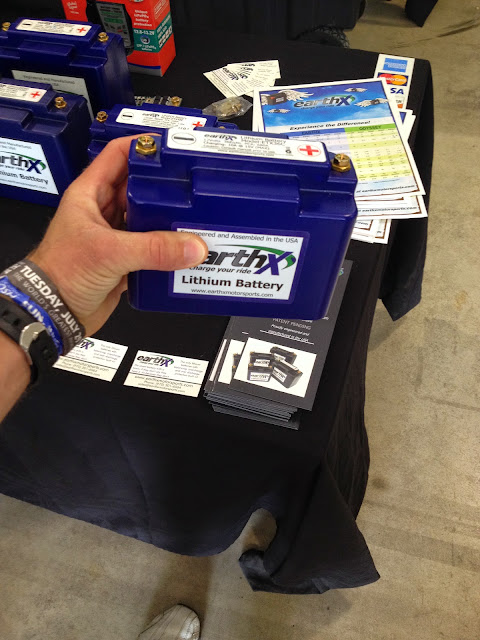
These are some new batteries from EarthX. They are Lithium Iron Phosphate and are a fraction of the size and weight. I really think I'm gonna use one of these instead of the lead acid battery. It'll save about 22lbs in weight!

All in all in it was a good trip. I learned a lot and finally met a lot of people in person. The plane should be done by this time next year which will make the logistics of getting up there a lot easier....an exciting thought.