Friday, August 30, 2013

Foot Well Panel

I was tired of the careful stepping and balancing acts required to avoid the angles in the floor of the foot well and needed a better place to work from inside the airplane. So I decided to go ahead and install my floor pans into the foot wells. The floor pans are a very tight fit and like other builders I decided to just drill and dimple the parts on there own outside of the aircraft. The angles they attach to are already drilled and dimpled so I don't see any harm in this.
 
Then disaster, frustration, and high blood pressure ensued.
 
During the installation of my LH Floor Pan, a very tight fit, while trying to push slowly into position it snagged and slipped and wound up bending. This bending caused the side flange to buckle and the buckle caused a crack around a rivet hole. Pulling the part back out was a nightmare. I cussed, sweat dripping down my face, blood pressure soaring, this task was infuriating. It turns out the small cutouts that are designed to go around the frames of the bulkhead were too small, snagging and binding the pans during the installation.
 
I calmed down...sulked...got some iced tea....and went back to the shop....now what?
 
I decided to remove and deburr the cracked area of the flange on the floor pan, only on the outboard side, inboard side was ok. I'm still maintaining proper edge distance from the adjacent rivets. I also opened the cutouts that were causing the trouble large enough to clear the frames and slid the part back into position. I didn't think cutting out the cracked flange would be any problem structurally since it's just a floor pan or aesthetically since it will all be hidden behind carpet. But just to be sure I figured a second opinion wouldn't hurt so I sent an email to Vans's. They responded with:
"I see no problem with you removing the crack as you did form the floor panel."

Good....I continued building.


Date and Time
Mon 26 -1.0hr- Drilled and deburred parts
Tues 27 -2.25hrs- Deburred and dimpled parts
Wed 28 -2.0hrs-  Finished dimpling, back riveted stiffening angles, riveted access panel doublers


Insulation installed under foot wells.
 
 
Material removed from cutout to clear the frames.

 
Floor Pan in position inside foot well.

 
Area cut from floor pan angle.


I primed and installed the access hole doublers in baggage floors. I also back riveted all the stiffening angles and nutplates.


My Shop....AKA: THE AIRPLANE FACTORY.

Monday, August 26, 2013

Baggage Area Work

Time for another update.

Date and Hours Worked
20 -1.25hrs- Cut insulation
21 -1.25hrs- Clecoed baggage skins, drilled seat hinges
22 -1.5hrs- Drilled, deburred, dimpled foot well floor panels, cut insulation
24 -2.0hrs- Started Floor Pan installation (more on this later)
25 -6.25hrs -Drilled baggage area floors, access panel cutouts, insulation, conduit, match drilled side panels, made stiffening angles for floor panels


One advantage of where I work is having access to some nice avionics tools and the people that know how to use them. Which is why the installation of the BNC connectors for my VHF Comm antennas look really nice.


Most of the baggage area panels clecoed in place and ready for match drilling.

I located the LH and RH access panels (using the stall warning access panel and doubler along with an extra I ordered) as far outboard as I could. The limiting factor is the side panels.


I cut out the access holes. It's pretty easy, just follow the stall warning access panel installation instructions.


I got the conduit installed. I made some little clips to attach the zip ties to and just pop riveted them in place.
 
I've got two tubes on the right and one on the left. I enlarged the holes in the aft bulkhead to fit the conduit through and then supported it with the clips in the baggage area.
 
 
The RH outboard conduit attaches to the same clip in back but snakes through the rib lightening hole and will come up through the floor panel. All of the wire will hide behind the side panel and can pass along the side of the airplane through the existing holes in the frames. 


I drill a hole in the seat rib for the com radio cable. This will then pass through the seat skin as well.

 
I made the stiffening angles for the baggage area floors.


Monday, August 19, 2013

Steps, Antennas, and Stuff

A lot of work has been completed, but I lack that exemplary feeling of joy after completing a section or part that I normally get. I suppose this felt more like a lot of small chores that needed to be done in order for me to move on to those larger tasks. Don't get me wrong, this was still a lot of work.

Tues 13th - 1.75hrs- Started upper forward fuselage section
Wed 14th -0.5hrs- Measured for antenna install, made spacers for step
Thur 15th -1.0hrs- Worked on upper fuselage, bent panels, drilled out holes
Sat 17th -6.5hrs- Made antenna doublers, drilled skin for antenna install, primed parts, installed stainless steel heater boxes, made clips for wiring conduit
Sun 18th -5.25hrs- Installed side panels, installed steps


I didn't get very far on the upper forward fuselage section. I just clecoed parts, drilled holes, made a stiffener out of extrusion, and then clecoed to the aircraft.


I ordered and installed the stainless steel heater boxes instead of Van's aluminum ones. Stainless Steel's thermal conductivity, or K-value, is a fraction of aluminum's; meaning that the stainless steel heater boxes will insulate the tunnel from the heat better than aluminum. Hopefully, this keeps the tunnel's heat cooler than what it would originally be. Also, in the event of an engine fire the aluminum would just turn into a puddle from the heat but the stainless steel would still be there. I also installed the boxes with a high temp silicone gasket (note the white tube in the pic below was shipped with the boxes) and some 3M fire barrier sealant around the edges to help keep the fumes out.


The Com Antennas Install has begun!
See my previous post for what my plan is for these antennas as well as dimensions and a discussion on the doubler sizing. I made the doubler first, per the dimensions I show on the previous post, and then I drilled out the rivets on the outboard frame since they will be incorporated into the doubler install. I match drilled the existing holes into the doubler and then match drilled the doublers holes to the skin.


I then drilled the large center hole in each part, deburred, dimpled, and primed everything. Here is a pic looking down and forward on the left hand installation location.
 
The doublers and shims dimpled and primed.


  The antenna clecoed in place.


 I finally got around to installing the side vent doors.


The step install.
I am installing these a little differently than what the plans say to do. I am using 1/4in hardware instead of #10 and I am installing it at angle instead of straight up and down. This will allow removal of the bolt in the future through the access panels I will be installing in the luggage compartment floor. I also made spacers from delrin rod to insert into the step tube to reinforce the tubing and prevent it from being deformed while tightening the bolt. I made them from delrin because it's cheap, I think it was around $3 for the rod I bought, and it wont cause dissimilar metal corrosion sitting inside the step.

 I made a makeshift insertion and positioning tool from pvc and safety wire.

 The step installed. It's a little scratched from sliding it in place, but I can touch that up later.

 View from the outside and the "shin protector" is installed.


Com Antenna Installation Plan

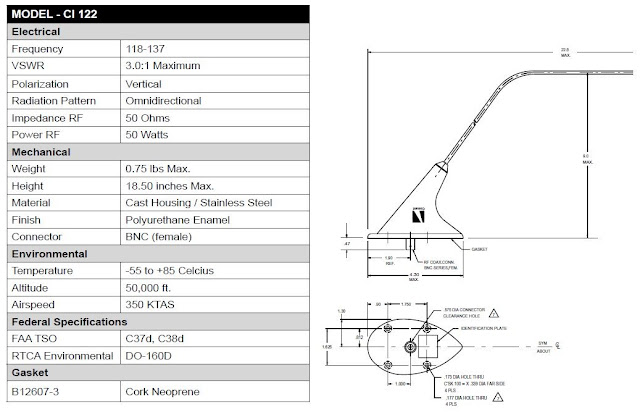
I am installing two Comant CI-122 VHF Communication antennas on the belly of the aircraft. The location I chose is used by a lot of RV-10 builders in the past and seems to be a good location with plenty of reception. They will be installed under the back passenger seats in the second bay from the most outboard on both sides. The antennas are designed specifically for mounting to the underside of an aircraft providing excellent radiation coverage for air-to-ground VHF communications on the 118-137 Mhz frequency range.


A 5/8in hole needs to be cut in the bottom of the aircraft to accommodate the BNC connector on the antenna. Standard practice dictates that aircraft antenna installations require a doubler to be made to reinforce the area that the hole has been cut in the skin and support the weight and pull of the antenna. A simple structural analysis of the lost strength in the skin shows that the 5/8in hole cut in the bottom skin, made of 0.032in 2024-T3 clad aluminum, requires at least 4.4 AD3 rivets in each quadrant of the doubler to replace the strength. Also, the doubler will be made of the same type and thickness as the aircraft skin.

I designed this doubler to support the antenna and reinforce the aircraft skin. You can see: the outline of the footprint of the antenna, the 5/8in hole in the center, 4 larger holes for the antenna screws, and several smaller holes for the MS20426AD3 rivets. Note there are at least 4.4 rivets in each quadrant of the doubler with the rivets in each corner being split by each quadrant.

 
The antenna can be grounded directly through the bottom of the antenna, which is bare metal, or through the screws that install it. The best ground method is through the bottom of the antenna and therefore I will not be using the cork neoprene gasket that is supplied with the antenna. After installation, the antenna will be sealed around all faying surfaces with pro-seal to prohibit corrosion.
 
I created a 3D model to show my intended installation. The doubler is the yellow part, a shim of 0.025" thickness is the bluish part, and the rest are the frames, seat stringers, and skin of the aircraft.

View looking down and forward into aircraft.

Wednesday, August 14, 2013

Completed Structure Overview (755.0hrs)

I wanted to make another overview post to show a little more accurately the parts I am working on. Currently, I have a lot of sections I'm working through simultaneously and will also be installing things that aren't in the plans.

For example, I'm working on: the step install, finishing the side skin vent doors, installing the heater boxes, building the upper forward fuselage, installing the luggage area floors, insulation and conduit, and the com antenna installs. So there is a lot of work coming up and I wanted to represent that in the Completed Structure Overview as best I could.

755.0 hrs Total Building Time    463.0  hrs is a mixture of tail and fuselage (still in work)
    292.0 hrs of the total belong to the Wings (includes times listed below)
       75.25 hrs to the Fuel Tanks
       25.5 hrs to the Ailerons
       26.25 hrs to the Flaps


Tailcone is Forever Attached

Wow! I can't believe it's been over a week since my last post....what happened?

It's been raining every afternoon here with these monotonous afternoon pop up thunderstorms. Which in turn cancels my efforts to go flying. Until Saturday morning! I FINALLY was able to squeeze in a 1.3hr flight, just long enough to shoot 3 instrument approaches and land before the lighting started striking again.

I spent the rest of the weekend working on the plane. I mainly worked on the tailcone attach section although I dabbled in attaching the steps as well.
In summary:
1. I ordered my Com Antennas, Stainless Steel Heater Boxes, and some hardware and materials I'll need for the step section (more on that when I do the work).
2. Deburred, countersunk, and riveted (what I could reach solo) tailcone and fuselage frames and skins.
3. While deburring I discovered a misdrill I made. I have no idea how it happened. I'll discuss my fix later with pictures.
4. Smoothed out the welds on the steps for a better appearance.
5. Attached the delrin block for the step.
6. I got a buddy to help and finished riveting the tailcone to the fuselage. So now the tailcone and fuselage will forever be one and that section is complete.
7. Got a small start on the upper fuselage section.

Time Log
Wed 7th - 1.5hrs - Made skin shims, drilled out tailcone holes, drilled new holes in bottom
Sat 10th - 3.5hrs - Deburred, dimpled, other misc work
Sun 11th - 5.5hrs - Started riveting what I could reach, started installing step
Mon 12th - 2.5hrs - Got some help finishing up the riveting. Also got a small start on the upper fuselage section.


This is the hole I misdrilled in the fuselage lower skin. I have no idea how it happened, but the little
snow man figure needs to go away.


I made a drilling template so I could center the new hole over the snow man. The new hole was drilled out large enough for a #5 rivet. I still had proper edge distance so moving up to a #5 rivet is really not a concern other than appearance and since this is on the bottom of the airplane that didn't concern me either.


The new larger hole (located to the right of the first rib on the left).
 
 
The new #5 rivet installed on the bottom of the aircraft. ...problem solved.


Baby's first time in the airplane!


Monday, August 5, 2013

New Shop Layout and Tailcone Attach


I had what was described as an ADD Saturday. I pilot friend of mine had free tickets to the Memphis Speedway, I've never been to anything like that before so we decided to fly to Memphis for a few hours to watch the races. The costs would be split 3 ways since we would be bringing a passenger with us as well. So, a cheap flight and free tickets, sounds like a great plan.

Saturday morning brought some large storms over the Memphis area cancelling our plans. So plan B; we'll fly East instead to Chattanooga for the day and do some zip-lining, sounds like a great plan.

The storms are moving East and looks like by the time we tried to head back we would probably be stuck in Chattanooga. So Plan C; we'll fly around town and just shoot some approaches and get lunch.

Weather briefer states the storms will be in our area within 30 minutes, ok no flying today. So plan C; with nothing to do for the day the guys decided to help me rearrange my shop moving the wings to the loft and shifting the large work table to the side so I could position the airplane in the center.

So after a day of bouncing from one idea to another it turned out to be a very productive afternoon. All the finished parts: wings, ailerons, flaps, vertical stabilizer, rudder, elevators, horizontal stabilizer are all stored in the loft. All the piece parts have been moved down and on the shelves for easy access. And the entire shop rearranged to make room for what was about to become something that resembles an airplane.

The next day I called a good friend of mine to stop by for a few hours and help me finish riveting the aft skin of the tailcone. Being the lightweight of the two of us I laid down some blankets and crawled into the tailcone. I good day to be a smaller guy, but still very tight and uncomfortable. We finished the skin and started lining up the two parts, tailcone and fuselage, for what I hope will become a very long relationship between the two. It was pretty easy and went a lot faster than I thought it would. I then swept up the shop, sat down, and just stared at it for a while....awesome.

Total time over the weekend - 6hrs
(including moving airplane parts, riveting the tailcone, and clecoing the tailcone to the fuselage,
not counting sweeping the shop and moving tools)


The shop's new layout.


Sunday, August 4, 2013

Friday, August 2, 2013

Static System and Another Vacation

Another vacation makes for a break in building the plane and it's updates. Yep, we took another vacation, this time boating with the in-laws. This is a yearly trip for us and I can't wait to be able to fly to the lake instead of driving the 10+ hours. I currently rent an airplane when I need to fly, but renting an airplane is only feasible if it's for a short trip. A week long boating venture would cost me a great deal as I would pay for the airplane to sit on the ground all week (major negative to renting). So, we load up the car every year and begin our trek. This year we had the baby for the first time which slowed us down a little, but the trip was long before she came along, so what's the difference.

After returning from vacation and completing my duties around the house I was able to get back to the plane. With the wings being finished it's time to prep the tailcone for attachment to the fuselage. The first step was installing the static system. As I stated in an earlier post I am using the SafeAir1 pitot/satic kit. I installed the static system before installing the aft skin on the tailcone for accessibility to the area. The static system install was easy and I finished everything in a few short nights. Next is riveting the aft upper skin and then the big shuffle day when the wings move to the loft and the whole shop is rearranged in preparation for the tailcone install.

Mon 29th -0.75hrs- Started static system install
Tues 30th -1.25hrs - Prosealed static ports in place, made adel clamp tabs for stringer
Wed 31st - 1.5hrs- Riveted tabs to stringer, installed clamps and hose


Static tubing runs from each static port to a tee and then down the upper LH stringer.


I made little tabs to attach the adel clamps to. This avoided drilling large #10 screw holes in the stringer. They are attached using two 470AD3 rivets.


The static ports are installed with Proseal. Riveting the ports in place can create a puckered look in the skin caused by having so many rivets in a close proximity. The proseal is still drying and I plan on giving them a good test pull to be sure they are secure.....otherwise I'll try plan B - rivet in place anyway.

Prosealing the ports in place does make a really nice finished look.


Back of Static port. The adel clamp picks up an existing tooling hole in the frame.


I made a small angle to attach the tee port to. It attaches in place using an existing hole as well.


"I'm ready to go swimming!"