
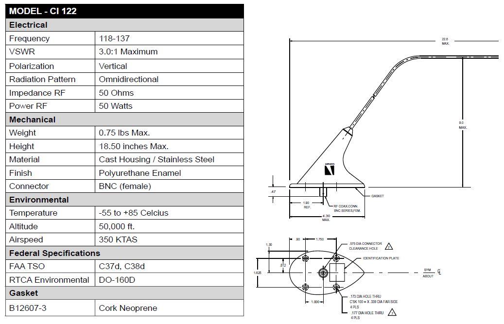
A 5/8in hole needs to be cut in the bottom of the aircraft to accommodate the BNC connector on the antenna. Standard practice dictates that aircraft antenna installations require a doubler to be made to reinforce the area that the hole has been cut in the skin and support the weight and pull of the antenna. A simple structural analysis of the lost strength in the skin shows that the 5/8in hole cut in the bottom skin, made of 0.032in 2024-T3 clad aluminum, requires at least 4.4 AD3 rivets in each quadrant of the doubler to replace the strength. Also, the doubler will be made of the same type and thickness as the aircraft skin.
I designed this doubler to support the antenna and reinforce the aircraft skin. You can see: the outline of the footprint of the antenna, the 5/8in hole in the center, 4 larger holes for the antenna screws, and several smaller holes for the MS20426AD3 rivets. Note there are at least 4.4 rivets in each quadrant of the doubler with the rivets in each corner being split by each quadrant.

The antenna can be grounded directly through the bottom of the antenna, which is bare metal, or through the screws that install it. The best ground method is through the bottom of the antenna and therefore I will not be using the cork neoprene gasket that is supplied with the antenna. After installation, the antenna will be sealed around all faying surfaces with pro-seal to prohibit corrosion.
I created a 3D model to show my intended installation. The doubler is the yellow part, a shim of 0.025" thickness is the bluish part, and the rest are the frames, seat stringers, and skin of the aircraft.

View looking down and forward into aircraft.
No comments:
Post a Comment