Ignition Fan
The Lightspeed Ignition boxes need forced air into them for cooling. This isn't a super critical item so I found a small 12 volt fan on Amazon for a couple bucks. Then made a manifold from aluminum sheet and tubing. After gluing it in place with JB Weld the two are now inseparable. For an added measure I wired this fan to the VPX and it will display a warning if the fan quits operating, otherwise I would never know it quit working.
Instrument Panel Switches
Started cutting the holes for the switches. Lots and Lots of wires will wind up in this area.
Wiring up the switches. A little safety note. You should have an individual ground for every switch because you do not want one ground coming loose and disabling all of your important switches. After testing out the switches in the plane, in the dark, I noticed they were REALLY bright. So I added a dimmer. This will probably be set to a certain brightness and then forgotten so I installed it behind the instrument panel. But its still accessible while flying if need be.
Not the best shot of the switches installed.....maybe there will be something better later on....sorry.
Showing posts with label lightspeed ignition. Show all posts
Sunday, April 19, 2015
Thursday, February 26, 2015
Lightspeed Ignition Part 1
Starting the Dual Lightspeed Ignition Install.
Here is a picture of all the parts that come in the kit. Sparg plugs, wires, the two control boxes, engine mounts for the sensors, and several other things.
I started with the step that made me the most nervous....drilling and tapping this VERY epensive engine. First you need to remove one of the propellor bushings that are pressed into the crankshaft. I used a wrench and two c-clamps....and some gentle taps from the hammer. Not gonna lie this was a pain in the butt.
With the bushing removed I marked and drilled the location needed for the engine sensor mount. I taped off the drill to mark the depth....I really didn't want to go too deep....that would be bad.
Once I drilled the holes I could tap the holes in the engine block.
Next I started making a mount plate for the ignition coils. Here is the intitial test fit.
After the test fit I learned where it could be trimmed up. Then I riveted the mount flanges in place, painted it with high temp paint, and bolted it to the engine mount using Adel clamps.
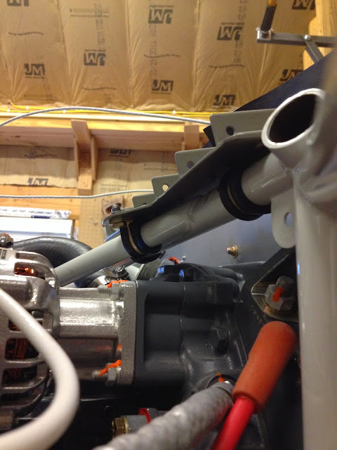
Here is a view from the under side to see the Adel clamps. Three Adel clamps, one of which is on the angled bar, allows for a solid install.
With the plate in place I screwed the ignition coils in place.
Ignition coils screwed in place with mechanical locking nuts, not nylon locking nuts. They're better for high temp areas.
The spark plug wires that come with the kit aren't long enough for half of the install so I had to make my own....actually very easy to do.
Here is the initial test fit of the spark plug wires I made. They still need to be secured in place.
Other side....you can see I started securing the wires in place with little tabs that attach to the lower valve cover screws.
Here is a picture of all the parts that come in the kit. Sparg plugs, wires, the two control boxes, engine mounts for the sensors, and several other things.
I started with the step that made me the most nervous....drilling and tapping this VERY epensive engine. First you need to remove one of the propellor bushings that are pressed into the crankshaft. I used a wrench and two c-clamps....and some gentle taps from the hammer. Not gonna lie this was a pain in the butt.
With the bushing removed I marked and drilled the location needed for the engine sensor mount. I taped off the drill to mark the depth....I really didn't want to go too deep....that would be bad.
Once I drilled the holes I could tap the holes in the engine block.
After the engine was drilled and tapped I could try out the mounts. They need some tweaking to even make the installation work; which is a bit annoying when you spend this much on an ignition system. But I get that they try and make it work for every engine.
Next I started making a mount plate for the ignition coils. Here is the intitial test fit.
After the test fit I learned where it could be trimmed up. Then I riveted the mount flanges in place, painted it with high temp paint, and bolted it to the engine mount using Adel clamps.
Here is a view from the under side to see the Adel clamps. Three Adel clamps, one of which is on the angled bar, allows for a solid install.
With the plate in place I screwed the ignition coils in place.
Ignition coils screwed in place with mechanical locking nuts, not nylon locking nuts. They're better for high temp areas.
The spark plug wires that come with the kit aren't long enough for half of the install so I had to make my own....actually very easy to do.
Here is the initial test fit of the spark plug wires I made. They still need to be secured in place.
Other side....you can see I started securing the wires in place with little tabs that attach to the lower valve cover screws.
My helper.
Subscribe to:
Posts (Atom)