Thursday, September 25, 2014

Baffled

Things are moving quickly from one task to another now and it's getting really difficult to keep track of what I'm working on, when, and for how long. The baffles are the last big item to build. So it deserves its own post. 

I had a a soon to be RV builder stop by the shop a few Saturdays ago. He asked to hang around for a while and rivet on some practice pieces while I supervised and advised. He said he learned a lot, so I guess it went well.

The baffles aren't bad. It brings you back to the "good-ol-days" of just smashing rivets and bending tin. 

The times listed below are a mix of many different things including: baffles, oil cooler install, air intake in cowling work, etc.

Time and Dates
Sat 6   -2.5 hrs 
Sun 7  -5.25 hrs-
Mon 8  -1.25 hrs
Tues 9  -1.25 hrs
Fri 12  -7.0 hrs
Sat 13  -5.5 hrs
Sun 14  -5.0 hrs


Cool shot from the loft of the shop.

After the aft baffle parts are riveted together I installed the untrimmed parts for a test fit.


Getting the aft baffles on is a PITA I wound up scratching up the valve covers. I taped them up to protect them from any more scratches.

On the LH air ramp I didn't follow the directions for trimming the part. I instead trimmed it as the marked in the picture. If you follow the directions you could have some edge distance issues with rivets in the next couple steps of the instructions.

RH air ramp bent up and clecoed in place.

LH air ramp bent up and clecoed in place.

This shows how much extra material you're dealing with on the air ramps. Things will get trimmed, A LOT, later.

I moved the scat tube intake farther back than the plans call for to prevent the lip of the cowling interfering.

This is the LH air ramp. You can see how my trim worked out. Nice edge distance on the fasteners.

I had to open the hole to clear the prop governor.

Here are all the components installed with the lower cowling in place. (Note the dancing in the background....I'm pretty sure she was entertaining Ayla :)

Next step was making the conical ramp corner gussets. I made a few templates from paper to get the idea of what kind of shape I would need. Then to the bend I gently rolled the aluminum with my hands on a piece of scrap tubing. It worked pretty well.

RH corner gusset cut and clecoed in place.
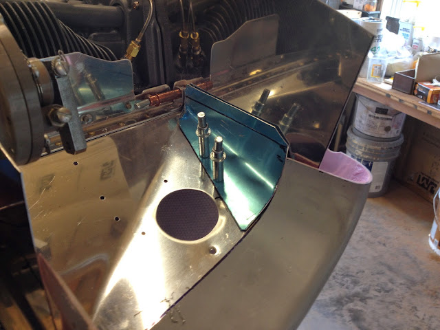
LH gusset cut and clecoed in place. I later had to remake this part. The bend I made on outboard baffle wound up pushing the ramp up 3/8 of an inch higher than the cowling lip. So I had to drill out this gusset shown and remake another to allow the ramp to sit lower.

RH gusset riveted in place. I'm really happy with the way this turned out.

I then evenly space the cowling up 3.5" to make marks for my initial cut.

I made a mark 3.75" all the way around the baffling - 0.25" lower than the cowling top - for my initial cut. I cut to that line then placed paperclips around the perimeter of the baffle. Placing the cowling back on pushed the paperclips down. Then I could go back and measure 0.5" from the top of each paperclip and this would give the points I need to have 0.5" clearance all the way around the perimeter of the baffle.

Made the cut and then removed the baffles and prepped for paint. A pile of twisted angled parts.

Monday, September 8, 2014

Selling Some Stuff

I am selling all of my Dynon equipment. See post on VAF Classifieds if you're interested.


Tuesday, September 2, 2014

Filtered Air Box Alt Air Door Redo

A few posts ago I had a picture of my FAB with fiberglass layed out to make an alternate air door. Well, I had a real hard time getting the piece of aluminum I was using as a spacer back out of the glass I layed up. While I was pulling and cussing and pulling more I realized that the glass wasn't really adhered to the box very well. And eventually it all just popped right off. SO...back to the drawing board for the alternate air door. I should have trusted my instincts and made if from aluminum in the first place.

Mon (Labor Day) Sept 2 -2.75hrs- Worked on Filter Air Box and final install of throttle body

Here are the pieces that make up the alternate air door. Bottom plate, two middle spacer strips that are bit thicker than the sliding plate, two upper retaining strips, and one strip across the back to act as a stop.

The four center holes fall inside of the filter so those will be riveted in place with button heads to the FAB. The outer rivets are countersunk since they fall under the filter.

Here is a pic of the door installed. The four center holes on each side of the strips attach to the FAB and the outer ones along the forward and aft edge are just countersunk as you saw in the above picture. Also you can see that instead of fiberglassing a tube into the box bottom for a drain tube, I went a different route. I used one of Vans unused static port compression fittings and cut the threaded part down to the thickness of the FAB. Then installed it into the box and globbed up some flox epoxy and glued it in place. With the compression fitting installed I can swap out the tube if I need to. It also seemed like an improvement over the original idea and was easier to install.

I made a little hat channel to attach the cable hardware to.

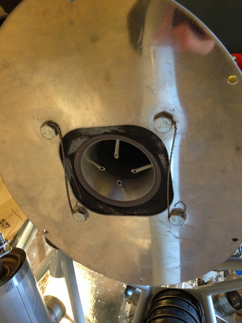
This is a picture looking up at the the throttle body. The throttle body was installed per Lycoming Service Instruction No. 1484C. Then the upper FAB plate is bolted on and safety wired.

The FAB clecoed in place.

I currently have the baffle material on the inside of the FAB neck, but after thinking about it I would prefer to have it on the outside. My thoughts were that this would be better for airflow, but if a piece of that tore loose it would really block air intake. So, I'm gonna drill it out and move the material to the outside. Then I can finally finish the cowling transition piece that slides into the FAB opening.

Exhaust is Installed

My In-laws were in town over the weekend and what better way to enjoy Labor Day weekend than installing exhaust on an IO-540 engine. OK...I can think of a lot of things that would have been more fun but it was still a good time hanging out in the shop and tinkering around on the plane. With help from my Father In-law we casually worked on the exhaust from start to finish in just a couple days. The job was pretty easy and it felt great starting and finishing a section in such a short amount of time.

Sat and Sun 30-31 -4.0hrs- Started and finished the exhaust.

Pretty easy section. Followed the plans with no surprises or issues.    ....doesn't the engine looks much cooler with the exhaust on?!

The heat muff is suspended from brackets and rubber linkages. It's easy to figure out once everything starts coming together. It was a lot of help having an extra set of hands for all the Adel clamps and such.


You just follow the numbers for each cylinder and everything starts lining up.


I was concerned about the clearance between the fuselage and the cowling. There are plenty of ways to tweak the position of the exhaust and I'm happy with the clearance I got on both sides. Once everything is installed I was surprised how solid everything is. You can shake the plane by pulling on the heat muff.

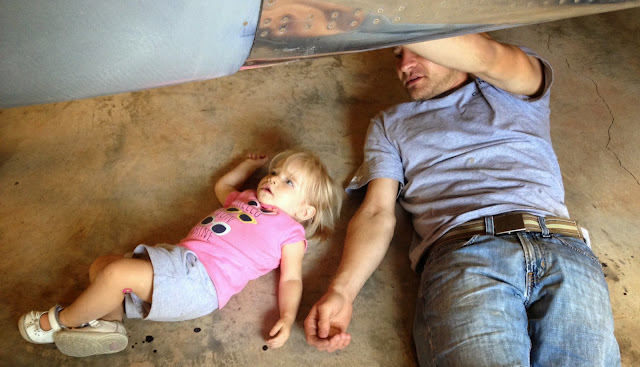
Here is the shop lead technician hard at work! (note the tools hanging from her pockets).

She had to inspect my work. It was approved!...whew.

Friday, August 29, 2014

Completed Structure Overview (1320.25hrs)

I just got caught up on a lot of posts and I'm just going to report my times here. It's becoming increasingly difficult to log the times into categories because you start to do a lot of different tasks at this point in the build.

August Times and Dates
2    -5.0 hrs- spinner and prop install
3    -5.5 hrs- cowling work
9    -5.25 hrs- cowl work...im pretty sure
10  -4.0 hrs- cowl stuff maybe
11  -1.0 hr- cowl hinge work
12  -1.25 hrs- cowl hinge work, installed prop governor
13  -1.5 hrs- cowl hinge work, air ramps
15  -7.0 hrs- engine work, cowl work, prop stuff, other stuff im sure
16  -4.75 hrs- same as above...too hard to document now
17  -3.25 hrs- engine stuff...i think

Sorry for the lack of detail but I can't promise it's gonna get better.

Total Time so far
1320.25

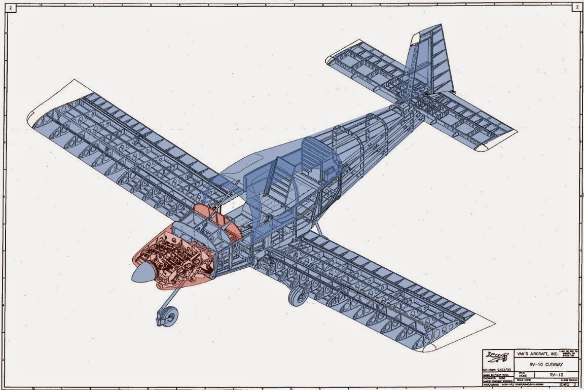
Red is in work. Blue is complete. ...as you can see eventually this little diagram won't be of use anymore.

Filtered Air Box

Catching up on posts still.

The filtered airbox at first seemed like it was going to be a lot of headscratching trying to figure it all out since the instructions are a bit lacking in the information department. But after I saw some pictures of what the end product was supposed to be it became pretty easy.

First I fluted the metal top to match the fiberglass bowl.

I then clecoed it in place allowing the filter sit just a little above the top so it would be completely closed out when I screwed the top plate into place.

I unbolted the closeout panel for the throttle body and let the little bit of oil drain out. Then I temporarily installed the throttle body in place for all the fitting. I didn't do a permanent install since it will have to come back off again when I fully drain the storage oil. The picture shows what is pretty close to the final install. You can see the cut out on the side that is required to clear the arm of the throttle. Pretty simple stuff. Cut the clearance out and match drill.

The air intake in the lower cowl has to be extended inside to meet up with the FAB. So they supply a foam block to help create the extra internal lip. I cut down the block to fit inside the lower cowl.

You're supposed to use the block to form the internal extension. This is a pic of the foam block in place with the lower cowl installed. You do need to trim the front of the FAB to allow for clearance of the lower cowl.

I then started carving out the inside of the foam block to make a "tunnel" from the lower air intake to the front of the FAB.

This produced a ring like this. ....this story will continue later....still working on this part.

I want to able to open and close the alternate air door (stock design only allows you to open and not close) from inside the cockpit. So I cut out my hole in the bottom of the FAB and then using a scrap piece of aluminum (taped up for a release agent) formed what will become a track for the air door to slide  back and forth in. I also fiberglassed my drain tube in place.

Thursday, August 28, 2014

Started Cowling

Continuing to catch up on the posts so I'll just let the pics go through everything.

As you can see the cowlings don't line up very well from the factory. The whole section is really just about getting them cut to size and having everything match up in the end. The instructions seemed to do things backwards then the way I thought you'd do them. So after thinking things through I decided to just approach cutting and fitting these like a wood working project. After I got in that mindset things went really well.


One thing I should note is that I made the cut out in the lower cowling for the front landing gear leg much wider than what the plans call for. The plans dimension is so tight I couldn't even install the cowling over the landing gear. So I increased it by (I think) about 0.75".

So I couldn't use the table saw to make a nice straight cut like I would for building furniture, so I broke out the laser level to mark a straight line from the ridges of the inner circle to the outboard edges of the cowling openings. I used the ridges as a guide to know when I had the cowling level. I then trimmed down the outboard inlets flush to the lines that were made from the laser level leaving the sides sticking up to be cut later.


With the front edge cut the two halves of the cowl could rest against each other and I was able to tape them up into place. First I taped up the bottom cowl and got it into place. I used some spacers up front against the spinner and then just duct taped the cowling to the engine to suspend it in place. The aft part of the cowling rested against fuselage skin.I then used an edge finder, just like I did with the doors, to mark the edge of the fuselage onto the cowling. I then cut the cowling along the line and re-installed it with a few clecoes into the hinge to hold it in place. I re-taped in place in front around the spinner with spacer blocks. I then repeated the process for the upper cowling and after I cut it I placed it in position. The pic below shows how well the fuselage and upper cowl lined up. I wound up increasing the clearance between the fuselage and cowlings all the way around to about 0.10" or so.

With the cowlings clecoed in place along their hinges the upper cowl side overlapped the lower cowl. I made a straight line mark using a chalk line positioned at the leading edge joint and the aft edge point. You can see how the upper cowling was not perfectly straight.

The entire time I had a chunk of scrap wood that was the right in the middle of the clearance tolerances listed in the instructions. I had a large piece spanning the upper joint and several tapped in position (as shown in the picture) around the lower opening. You can also see how the cowling sits just below spinner. I've heard you want to have this because the engine "settles" in place and will drop a bit.

I cut the upper cowling and then used a large flat sanding block to really flatten the cut out. I then clecoed the cowling back on and used the upper cowling to mark the cut line for the lower cowling. 

With the two halves cut and sanded I had zero clearance between the two halves. So I had to remove the upper half a few times and sand it down just to create some kind of gap between the two. I then installed the horizontal hinges per the plans except a bit shorter to accommodate the Aerosport Pin Covers.

Everything lines up pretty well. The only thing I need to do now is some body work around the openings.