Friday, September 13, 2013

Engine Cowling: Vans Vs Showplanes

There are two engine cowlings available for the RV-10: the standard stock Van's Aircraft cowling and the Showplanes Cowling. Showplanes is a side company that makes parts for experimental aircraft. I am really undecided about which engine cowling I want to install when the time comes. So I thought it would be fun to ask you...the reader.

The Stats

Van's cowling
-Cheaper
-Ships with the rest of the finish kit
-Install instructions remain the same

Showplanes Cowling
-Requires larger more expensive spinner
-Improves cooling (although I have only heard this, I have yet to see any empirical data)

There is probably more points to be made, but I guess the ultimate question I ask is,
Which one do you think looks cooler?

This part is important! For those non aviation types the engine cowling sits right behind the propeller. Look closely at the engine inlets, the lower air scoop, or lack of scoop, the general shape etc..DO NOT LIKE OR DISLIKE BASED ON PAINT COLOR!    ...Have fun and feel free to leave comments.

Don't forget to vote at the end!

Van's Cowling


Showplanes Cowling


Create your free online surveys with SurveyMonkey , the world's leading questionnaire tool.

Wednesday, September 11, 2013

Finished Baggage Area

Another trip....another small break from building. We flew down to Destin over Labor Day weekend for my Brother-in-law's wedding. The flight was quick (quick in Cessna 172 terms...faster than driving let's say that) and easy. A little over 2hrs and the baby slept the whole way there and back.
 
Back to building.
 
I finished the baggage area over the last weekend. I have a side panel that's not permanently installed since I'm waiting on more insulation. I also didn't install the seat belt guides yet since I'm not sure what I'm doing there yet. Jess wants retractable seat belts....can't blame her I do too. I have a plan of how I'm going to do this, but until I have the parts in hand the guides will stay off the airplane. I also finished the foot well pans.
 
Dates and Times
September
Wed 4th - 1.0hrs - Pop rivet floor pans.
Thurs 5th - 1.5hrs - Rivet floor pans.
Fri 6th - 0.5hrs - Changed conduit run on RH side of aircraft to extend to seat frame.
Sat 7th - 4.75hrs - Baggage area work. Pop rivets etc.
Sun 8th -4.0hrs - Finished baggage area and panels. Started baggage door.
Tues 10th - 0.5hrs - Drilled and countersunk hinge
 

Finished the side frames. I primed them with "rattle can" epoxy primer.

I changed the conduit to run all the way to the aft seat frame. This area will be closed off with a riveted in side panel.


All the panels installed.

Started the baggage door.


I always feel like someone is watching me...

Friday, August 30, 2013

Foot Well Panel

I was tired of the careful stepping and balancing acts required to avoid the angles in the floor of the foot well and needed a better place to work from inside the airplane. So I decided to go ahead and install my floor pans into the foot wells. The floor pans are a very tight fit and like other builders I decided to just drill and dimple the parts on there own outside of the aircraft. The angles they attach to are already drilled and dimpled so I don't see any harm in this.
 
Then disaster, frustration, and high blood pressure ensued.
 
During the installation of my LH Floor Pan, a very tight fit, while trying to push slowly into position it snagged and slipped and wound up bending. This bending caused the side flange to buckle and the buckle caused a crack around a rivet hole. Pulling the part back out was a nightmare. I cussed, sweat dripping down my face, blood pressure soaring, this task was infuriating. It turns out the small cutouts that are designed to go around the frames of the bulkhead were too small, snagging and binding the pans during the installation.
 
I calmed down...sulked...got some iced tea....and went back to the shop....now what?
 
I decided to remove and deburr the cracked area of the flange on the floor pan, only on the outboard side, inboard side was ok. I'm still maintaining proper edge distance from the adjacent rivets. I also opened the cutouts that were causing the trouble large enough to clear the frames and slid the part back into position. I didn't think cutting out the cracked flange would be any problem structurally since it's just a floor pan or aesthetically since it will all be hidden behind carpet. But just to be sure I figured a second opinion wouldn't hurt so I sent an email to Vans's. They responded with:
"I see no problem with you removing the crack as you did form the floor panel."

Good....I continued building.


Date and Time
Mon 26 -1.0hr- Drilled and deburred parts
Tues 27 -2.25hrs- Deburred and dimpled parts
Wed 28 -2.0hrs-  Finished dimpling, back riveted stiffening angles, riveted access panel doublers


Insulation installed under foot wells.
 
 
Material removed from cutout to clear the frames.

 
Floor Pan in position inside foot well.

 
Area cut from floor pan angle.


I primed and installed the access hole doublers in baggage floors. I also back riveted all the stiffening angles and nutplates.


My Shop....AKA: THE AIRPLANE FACTORY.

Monday, August 26, 2013

Baggage Area Work

Time for another update.

Date and Hours Worked
20 -1.25hrs- Cut insulation
21 -1.25hrs- Clecoed baggage skins, drilled seat hinges
22 -1.5hrs- Drilled, deburred, dimpled foot well floor panels, cut insulation
24 -2.0hrs- Started Floor Pan installation (more on this later)
25 -6.25hrs -Drilled baggage area floors, access panel cutouts, insulation, conduit, match drilled side panels, made stiffening angles for floor panels


One advantage of where I work is having access to some nice avionics tools and the people that know how to use them. Which is why the installation of the BNC connectors for my VHF Comm antennas look really nice.


Most of the baggage area panels clecoed in place and ready for match drilling.

I located the LH and RH access panels (using the stall warning access panel and doubler along with an extra I ordered) as far outboard as I could. The limiting factor is the side panels.


I cut out the access holes. It's pretty easy, just follow the stall warning access panel installation instructions.


I got the conduit installed. I made some little clips to attach the zip ties to and just pop riveted them in place.
 
I've got two tubes on the right and one on the left. I enlarged the holes in the aft bulkhead to fit the conduit through and then supported it with the clips in the baggage area.
 
 
The RH outboard conduit attaches to the same clip in back but snakes through the rib lightening hole and will come up through the floor panel. All of the wire will hide behind the side panel and can pass along the side of the airplane through the existing holes in the frames. 


I drill a hole in the seat rib for the com radio cable. This will then pass through the seat skin as well.

 
I made the stiffening angles for the baggage area floors.


Monday, August 19, 2013

Steps, Antennas, and Stuff

A lot of work has been completed, but I lack that exemplary feeling of joy after completing a section or part that I normally get. I suppose this felt more like a lot of small chores that needed to be done in order for me to move on to those larger tasks. Don't get me wrong, this was still a lot of work.

Tues 13th - 1.75hrs- Started upper forward fuselage section
Wed 14th -0.5hrs- Measured for antenna install, made spacers for step
Thur 15th -1.0hrs- Worked on upper fuselage, bent panels, drilled out holes
Sat 17th -6.5hrs- Made antenna doublers, drilled skin for antenna install, primed parts, installed stainless steel heater boxes, made clips for wiring conduit
Sun 18th -5.25hrs- Installed side panels, installed steps


I didn't get very far on the upper forward fuselage section. I just clecoed parts, drilled holes, made a stiffener out of extrusion, and then clecoed to the aircraft.


I ordered and installed the stainless steel heater boxes instead of Van's aluminum ones. Stainless Steel's thermal conductivity, or K-value, is a fraction of aluminum's; meaning that the stainless steel heater boxes will insulate the tunnel from the heat better than aluminum. Hopefully, this keeps the tunnel's heat cooler than what it would originally be. Also, in the event of an engine fire the aluminum would just turn into a puddle from the heat but the stainless steel would still be there. I also installed the boxes with a high temp silicone gasket (note the white tube in the pic below was shipped with the boxes) and some 3M fire barrier sealant around the edges to help keep the fumes out.


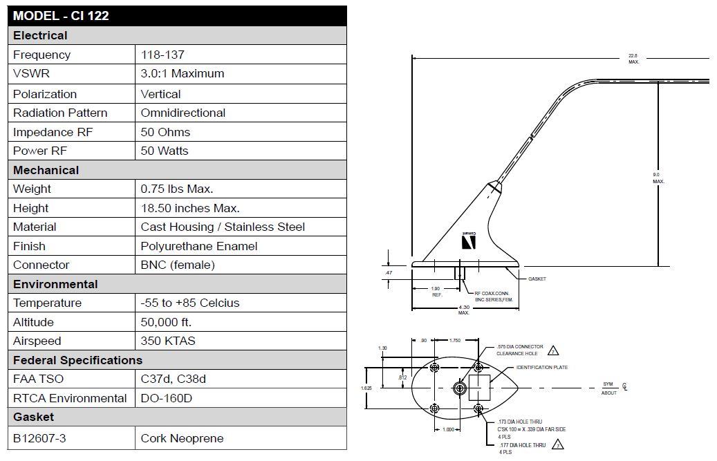
The Com Antennas Install has begun!
See my previous post for what my plan is for these antennas as well as dimensions and a discussion on the doubler sizing. I made the doubler first, per the dimensions I show on the previous post, and then I drilled out the rivets on the outboard frame since they will be incorporated into the doubler install. I match drilled the existing holes into the doubler and then match drilled the doublers holes to the skin.


I then drilled the large center hole in each part, deburred, dimpled, and primed everything. Here is a pic looking down and forward on the left hand installation location.
 
The doublers and shims dimpled and primed.


  The antenna clecoed in place.


 I finally got around to installing the side vent doors.


The step install.
I am installing these a little differently than what the plans say to do. I am using 1/4in hardware instead of #10 and I am installing it at angle instead of straight up and down. This will allow removal of the bolt in the future through the access panels I will be installing in the luggage compartment floor. I also made spacers from delrin rod to insert into the step tube to reinforce the tubing and prevent it from being deformed while tightening the bolt. I made them from delrin because it's cheap, I think it was around $3 for the rod I bought, and it wont cause dissimilar metal corrosion sitting inside the step.

 I made a makeshift insertion and positioning tool from pvc and safety wire.

 The step installed. It's a little scratched from sliding it in place, but I can touch that up later.

 View from the outside and the "shin protector" is installed.


Com Antenna Installation Plan

I am installing two Comant CI-122 VHF Communication antennas on the belly of the aircraft. The location I chose is used by a lot of RV-10 builders in the past and seems to be a good location with plenty of reception. They will be installed under the back passenger seats in the second bay from the most outboard on both sides. The antennas are designed specifically for mounting to the underside of an aircraft providing excellent radiation coverage for air-to-ground VHF communications on the 118-137 Mhz frequency range.


A 5/8in hole needs to be cut in the bottom of the aircraft to accommodate the BNC connector on the antenna. Standard practice dictates that aircraft antenna installations require a doubler to be made to reinforce the area that the hole has been cut in the skin and support the weight and pull of the antenna. A simple structural analysis of the lost strength in the skin shows that the 5/8in hole cut in the bottom skin, made of 0.032in 2024-T3 clad aluminum, requires at least 4.4 AD3 rivets in each quadrant of the doubler to replace the strength. Also, the doubler will be made of the same type and thickness as the aircraft skin.

I designed this doubler to support the antenna and reinforce the aircraft skin. You can see: the outline of the footprint of the antenna, the 5/8in hole in the center, 4 larger holes for the antenna screws, and several smaller holes for the MS20426AD3 rivets. Note there are at least 4.4 rivets in each quadrant of the doubler with the rivets in each corner being split by each quadrant.

 
The antenna can be grounded directly through the bottom of the antenna, which is bare metal, or through the screws that install it. The best ground method is through the bottom of the antenna and therefore I will not be using the cork neoprene gasket that is supplied with the antenna. After installation, the antenna will be sealed around all faying surfaces with pro-seal to prohibit corrosion.
 
I created a 3D model to show my intended installation. The doubler is the yellow part, a shim of 0.025" thickness is the bluish part, and the rest are the frames, seat stringers, and skin of the aircraft.

View looking down and forward into aircraft.

Wednesday, August 14, 2013

Completed Structure Overview (755.0hrs)

I wanted to make another overview post to show a little more accurately the parts I am working on. Currently, I have a lot of sections I'm working through simultaneously and will also be installing things that aren't in the plans.

For example, I'm working on: the step install, finishing the side skin vent doors, installing the heater boxes, building the upper forward fuselage, installing the luggage area floors, insulation and conduit, and the com antenna installs. So there is a lot of work coming up and I wanted to represent that in the Completed Structure Overview as best I could.

755.0 hrs Total Building Time    463.0  hrs is a mixture of tail and fuselage (still in work)
    292.0 hrs of the total belong to the Wings (includes times listed below)
       75.25 hrs to the Fuel Tanks
       25.5 hrs to the Ailerons
       26.25 hrs to the Flaps